
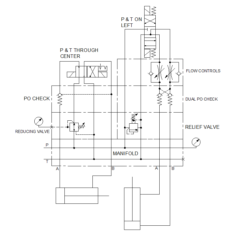
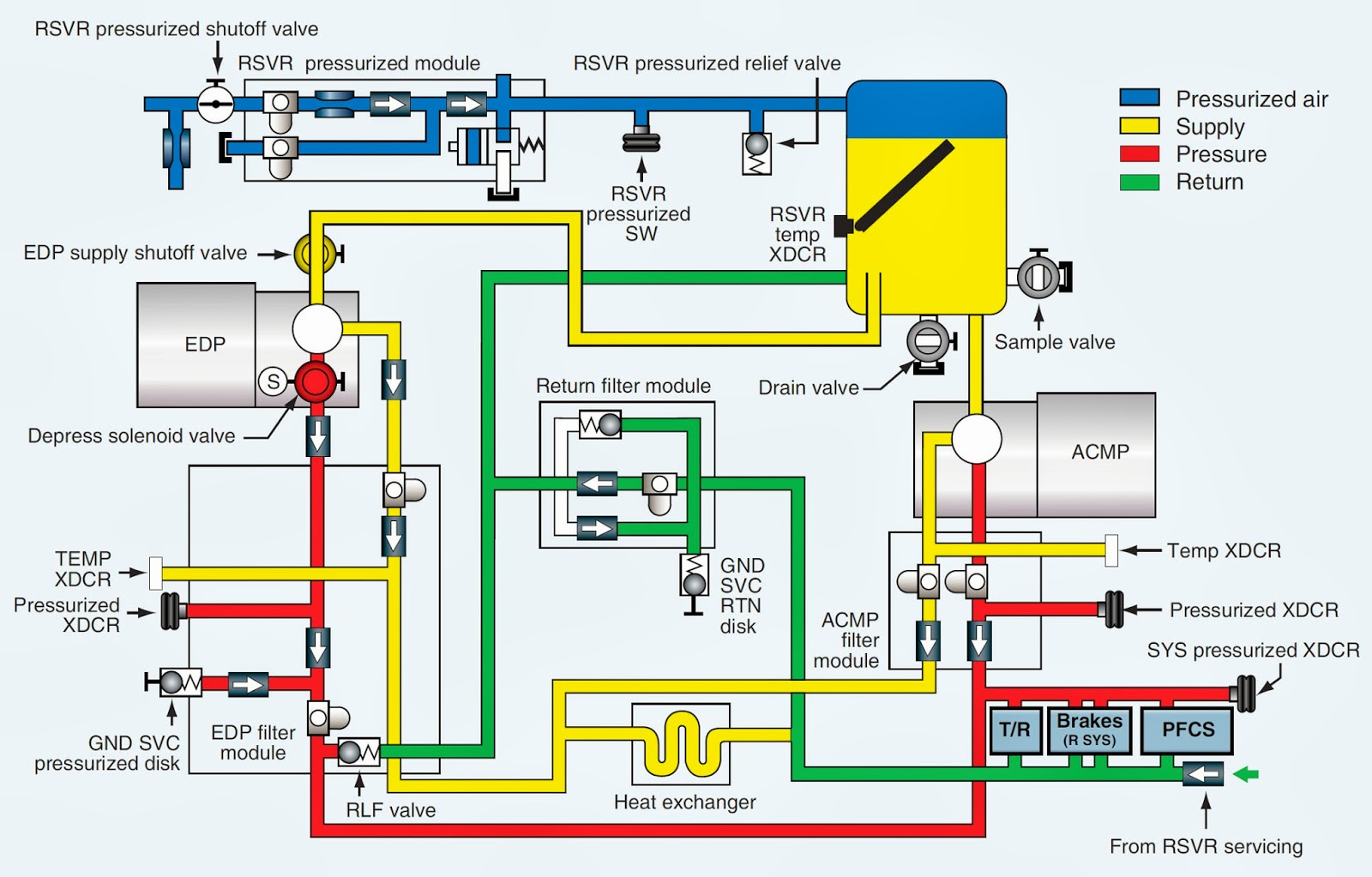
The hydraulic circuit diagram of a plant with two actuators. Download Scientific Diagram
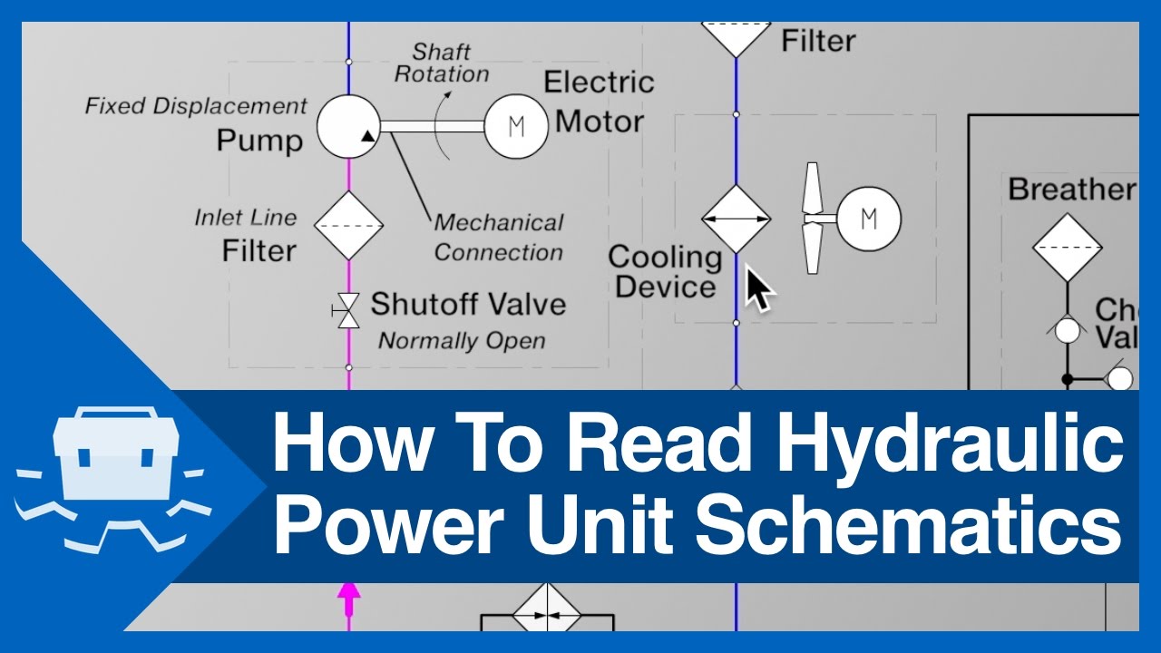
Schematic reading is one of the most important skills when working with complex hydraulic systems. We are going to spend a handful of videos looking at diffe.
How To Read Hydraulic Schematic Drawings Wiring Diagram
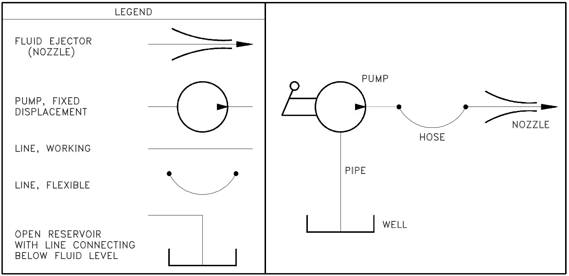
Reading fluids circuit diagrams - hydraulic & pneumatic symbols Dec 19, 2017 Below are some common illustrations of equipment located on fluids circuit diagrams, followed by descriptions of the most common elements. Later in this article series we will describe some simple hydraulic and pneumatic circuits composed of these circuit elements.

How To Read Hydraulic Schematics For Dummies Circuit Diagram
Below is our hydraulic symbiology glossary outlining elements of specific Carr Lane ROEMHELD parts, including check valves, power units, relief valves, control valves, pressure gauges, hydraulic circuits, variable displacement pumps and more. Carr Lane provides engineers with valuable resources.

How To Read A Hydraulic Schematic Circuit Diagram
The basic steps to reading a hydraulic schematic are: Identifying line types Identify if lines cross with or without connecting Identify the components Identify the flow path at a de-energized state Determine what happens as each valve is moved Activate multiple valves at a time to see if there are unintentional consequences.

How To Read A Hydraulic Schematic Diagram Wiring Diagram
A hydraulic circuit diagram is a complex visual representation of a hydraulic system. It shows the relationships between components and how they interact to produce a desired result. Understanding such diagrams is essential for any hydraulic engineer, maintenance engineer, technician or operator.

How To Read Hydraulic Circuit Diagram
We guide you through a simple hydraulic circuit by explaining the basic symbols, drawn to ISO 1219.We also demonstrate different levels of detail shown in 2.
How To Read Hydraulic Circuit Diagram
In this lesson we'll review schematic symbols for common fluid power devices including fluid conductors, prime movers, pumps, reservoirs, actuators, directio.

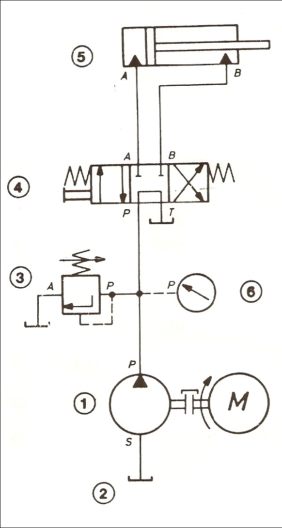
How to trace hydraulic circuit (Part 4) Double acting cylinder with variable load takes place
Business Industry Hydraulics Preview this course Learn to read and understand hydraulic circuit symbols Explaining fluid power symbols and how to interpret the hydraulic circuits that use them 3.7 (12 ratings) 73 students Created by Gary Molton Last updated 2/2021 English English [Auto] What you'll learn
How To Read Hydraulic Valve Schematics
The basics of how to read hydraulic schematics and recognize basic component types.
How To Read A Hydraulic Schematic Diagram Wiring Diagram
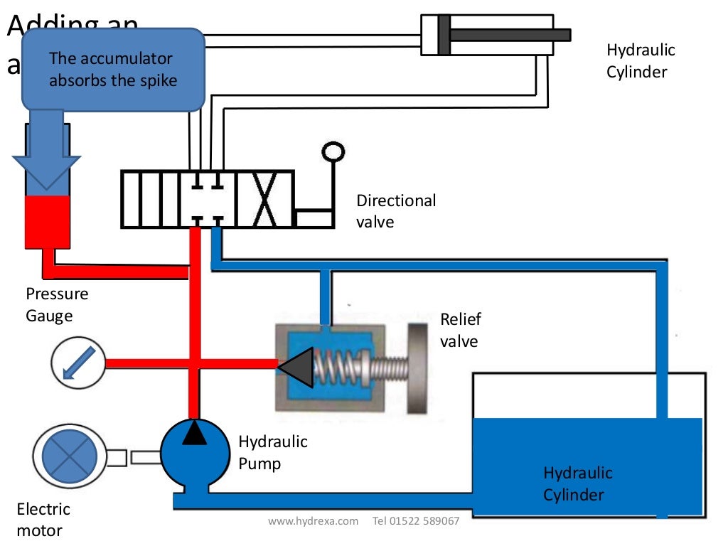
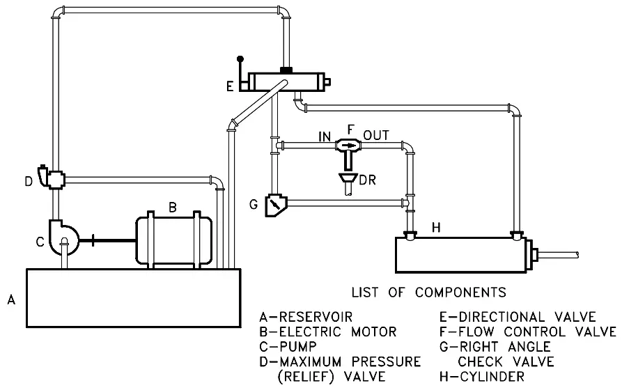
Reading Fluid Power Diagrams. Using the symbology previously discussed, a fluid power diagram can now be read. But before reading some complex examples, let's look at a simple hydraulic system and convert it into a fluid power diagram. Using the drawing in Figure 27, the left portion of Figure 28 lists each part and its fluid power symbol.
Hydraulic Circuit Diagram Animation
First things first - identify the symbols. Hydraulic schematics use a wide range of symbols to represent different parts and connections. Familiarize yourself with these symbols by consulting books or manuals that describe what each symbol stands for. This will make it much easier to interpret the schematic. Next, pay attention to the arrows.
How To Read Hydraulic Schematic
1. Identifying the line types In a hydraulic schematic, each line type has a unique meaning. In addition, colors can be added to indicate purpose of the line. In the figure below, all of the basic line types are shown. The basic line is a solid line that represents a working pressure hose or tube.
How To Read A Hydraulic Schematic Diagram Wiring Diagram
Understanding how to read hydraulic circuits is the key to designing, constructing, and troubleshooting your machines efficiently. The first step to reading hydraulic circuits is familiarizing yourself with the various symbols used to represent the components of the circuit.

Hydraulic Circuit Diagrams And Symbols
Basic Electrical Knowledge https://www.youtube.com/playlist?list=PL8zOygNOyBo1Nq53tdaSt1FfoIjMIV52FNEC PLAYLIST PRACTICE TESThttps://www.youtube.com/playlist.

how to read a hydraulic schematic Wiring Work
In general, when you first review a hydraulic schematic, you should use the following steps: Review the different types of lines. Determine where lines cross and where they connect. Identify each of the hydraulic components using our downloadable table: ISO Hydraulic Symbols. Determine the fluid flow direction.
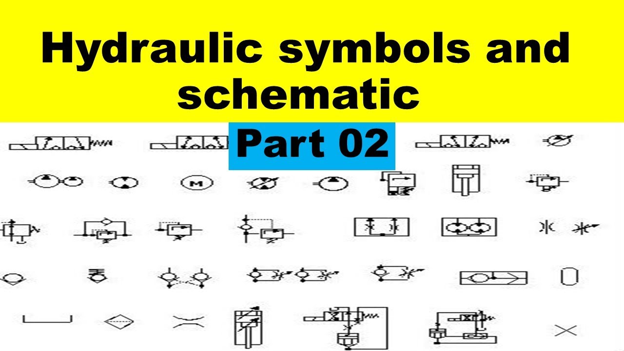
Hydraulic Symbols and Schematic For Beginners How to Read Hydraulic Drawing. Part 02
Pipelines Pipelines on hydraulic circuits are shown with lines connecting the elements. The control lines are represented by a dotted line. The direction of fluid flow is indicated by arrows, if necessary. Some lines are designated by letters: P - pressure line, T - line drain, X - control line l - drainage.